What is a Step-Down Transformer?
 |
| What is a down Transformer? |
A step-down transformer is a type of electrical transformer that decreases the voltage level from the primary winding to the secondary winding. In a Step-down transformer, the number of turns in the secondary winding is less than the number of turns in the primary winding. As a result, the output voltage is lower than the input voltage. Step-down transformers are commonly used to convert high-voltage, low-current power into low-voltage, high-current power. A transformer is a highly efficient machine with up to 95% efficiency.
Types of transformer W.r.t voltages
There are two types of electrical transformers one is
- Step-up transformer
- Step-down transformer
Construction of step-down transformer
- Winding
- Core
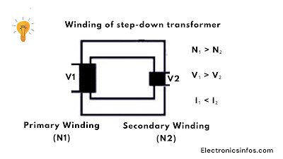
Winding of step-down transformer
Core of Step-down Transformer
Working Principle of Step-down Transformer
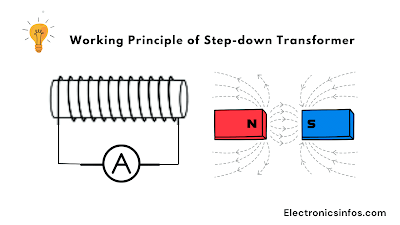
The working principle of the transformer is Faraday's law of Electromagnetic induction. When an alternating current (AC) is applied to the primary winding of a transformer, it creates a magnetic field around the winding. This magnetic field then induces a current in the secondary winding, which is proportional to the number of turns in the secondary winding. The induced current in the secondary winding produces a voltage drop across the winding, which is the transformer output voltage.
 | |
|
For example, if the primary winding has 1000 turns and the secondary winding has 500 turns, the voltage ratio would be 2:1, which means that the output voltage would be half of the input voltage.
There are two terminologies are used in the transformer One is HV and another one LV side. The HV sides mean The higher numbers of turns or high voltages with thin turns. The LV side means the low number of thick turns.
Types of Transformer w.r.t Core
Transformation Ratio formula
V₂ = Voltage produced at the secondary (load) winding of the transformer
N₁ = Number of turns in the primary winding
N₂ = Number of turns in the secondary winding
I₂ = Current flowing through the secondary windings
I₁ = Current flowing through the primary windings
In a step-down transformer, where the secondary voltage is lower than the primary voltage, the turns ratio is less than 1.
N₁ > N₂
V₁ > V₂
I₁ < I₂
For example, if a transformer has 1000 turns in the primary winding and 100 turns in the secondary winding, the turns ratio would be
N = 1000/100= 10
This means that the voltage in the secondary winding will be one-tenth (or 0.1 times) the voltage applied to the primary winding.
Applications of Step-Down transformer
- Power Distribution
- Electronic Devices
- Welding
- Voltages regulations
- Lighting
Faqs(Frequently Asked Questions)
The Voltage ratio is defined as The ratio of Vp and Vs. This ratio defines how much voltage is stepped up or stepped down. The ratio defines the K factor that tells the step-up transformer or step-down transformer.
The Transformer ratio is defined as the ratio between the primary turns (Np) to secondary turns(Ns).
There are 3 types of transformer w.r.t core, Shell and Berry type.
The Emf Equation of the transformer is 1.11 x 4f Φm = 4.44f Φm.
There are some conditions of the ideal transformer No leakage Flux No internal winding resistance zero Losses
Output power = Input power


0 Comments
please do not insert spam links