Top 5 Testing Methods of Electrical System
In 2024, the electrical installation industry continues to evolve with advanced testing methods to ensure safety, efficiency, and compliance with regulatory standards.
Among the top testing methods, the insulation resistance test remains crucial for preventing electrical shocks and fires by detecting deteriorating insulation. The polarity test is essential for verifying correct connections and preventing damage to electrical devices.
Continuity tests are conducted to ensure that electrical circuits are complete and that there are no open or broken paths.
Earth resistance testing is vital for the safety of installations, ensuring that the earth connection is effective in case of a fault.
Lastly, the short circuit test is used to determine the circuit's ability to safely withstand high currents resulting from a fault. These methods are integral to maintaining the integrity of electrical installations and protecting both equipment and personnel.
There are 5 tests we discuss in this article including
Electrical Test
- Polarity Test
- Continuity Test
- Insulation Test
- Short Circuit Test
- Continuity Test of Earth Connection
Polarity Test
The Polarity Test is a critical procedure in electrical installations to ensure that all connections are made correctly. It involves verifying that the live and neutral wires are connected in the proper manner
The test can be conducted using various methods, such as a test lamp, continuity tester, or a multimeter, depending on whether the supply is live or not.
- By Test Lamp
- By continuity Tester
- By Mager
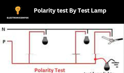
By Test Lamp
This method is used when ac supply is on. if we want to do a polarity test via a test lamp the method is shown below
Procedure
- shut off the all upper parts of the single-pole switch
- on the all-single pole switch
- all load disconnect from the circuit (LAmp, fans etc )
- all fuses must be in the circuit
- one terminal of the test lamp connects to the neutral terminal
- on the main switch
- the second terminal is connected to the switch
- if the lamp is on so it means the switch is in phase point
By continuity Tester
This method is used where the main supply is not present in the system so we use the continuity method for this purpose to ensure the polarity of the single pole switch.
Procedure
- disconnect all fuse, and lamps from the circuit
- on all single pole switches
- one terminal of the tester is connected to a fuse phase wire
- other terminals are used in every single-pole switch
- if the lamp is on this means the switch is on the phase wire
- if the lamp is off when we connect the terminals it means it's in neutral
By Mager
if we use a mager to test the polarity of a single-pole switch the method is the same as the continuity method. if we rotate the handle of the mager at a constant speed if the needle is in zero position it means the switch is proper polarity.
Continuity Test
The test ensures that there are no breaks or faults in the wiring. Typically, a continuity tester or a multimeter is used to perform this test. The device is connected to two points in the circuit, and if the circuit is complete, the tester will indicate continuity, usually through a visual or auditory signal.
This test is particularly important after installation and repair work to confirm that connections have been made correctly.
 |
| continuity test by multimeter |
Procedure
- disconnect all loads
- disconnect the lamps
- disconnect the fans
- switch off all switches
- one terminal of the continuity tester is connected with the one terminal of the switch
- another terminal of the continuity tester is connected with the other terminals of another switch
- if the lamp is on this means the same wire is used in both switches.
we also test this by using a mager the line wire and earth wire are connected with two different switches and rotate the handle of the mager at a constant speed if the needle of the mager shows 0 ohms it means the path is used in both switches which is show right direction of switches.
Insulation Test
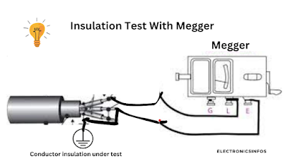
This test is used to ensure the insulation resistance of wires is enough. This test is crucial to identify potential faults or weaknesses in the insulation that could lead to electrical issues or safety hazards. There are different methods and instruments are used to find the insulation resistance of a wire. In This article, we used a mager for testing the insulation of wire.
Results
- High insulation resistance values indicate good insulation.
- Low insulation resistance suggests insulation breakdown or moisture ingress.
Procedure
- connect all load
- connect the bulb to the holder
- ón the fan's regulators
- on all switches
- connect both wires of the main switch to the other and connect this point to the line terminals of the mager,
- the earth terminals of the mager are connected with the water tap
- rotate the handle at a constant speed if
Note
- if the wire is V.I.R so the mager shows the 50mega ohm,
- if the wire is P.V. C the value is 12.5 Mega ohm.
Short Circuit Test
A short circuit test is used to ensure the safety of the circuit. This test is conducted where we need to know whether both wires of wiring are connected or not to each other, it is due to damage to insulation that connects to each other. if this happens that both wires are connected to each other a condition is called a short circuit in wiring. the result of this system is a huge amount of current is drawing in the wiring and all wires become hot and the result is that fire is developed in the wiring.to do this test the method is described below
Procedure
- cut off all load
- cut off the lamps
- cut off all machines
- all fuses present in the system
- switch on the regulators
- the main wiring of both terminals is connected to the mager line and earth terminals respectively
- rotate the mager handle at a constant speed
Results
- if the needle of the mager shows an infinity value or some value its means no short circuit is present in the wiring
- if it shows '0' it means a short circuit is present in the wiring.
Continuity Test of Earth Connection
A continuity test is used where the conduit system is used in the wiring system. because all pipes earth at a single point. this test ensures the continuity of the earth connection. for this purpose, we use a mager to check the continuity of the earth's connection.
we use one line terminal of mager and connect to the one side of the pipe and another terminal of the earth is connected with the other side. after that, we rotate the handle at a constant speed if it shows zero ohms it means continuity is good if it shows infinity this means the connection is loose. IEEE Regulations specify a resistance of 1 ohm.
Conclusions
The insulation resistance test confirms the integrity of electrical insulation, preventing potential hazards. The polarity test ensures that the electrical systems are correctly connected, which is crucial for the safety and functionality of electrical appliances.
Continuity tests affirm the reliability of electrical circuits. Earth resistance testing guarantees a safe path for fault currents.
Collectively, these tests provide a comprehensive safety check, ensuring that electrical installations are performed to the highest standards, reflecting the industry's commitment to safety and excellence.
Frequently Asked Questions – FAQs
What is the purpose of insulation resistance testing?
Why is polarity testing important?
How does continuity testing contribute to electrical safety?
What does earth resistance testing indicate?
What is the significance of the short circuit test?
Related Posts
Surge Protectors Vs Power Strips
Electrical Safety Training Tips
5 Battey Backup Surge Protectors
5 Best Digital Temperature Sensors


-Electronicsinfos.png)


0 Comments
please do not insert spam links